Home Page > 15kiloWatt Standby Generator |
Updated: 2013-07-21 |
15kW Residential Standby Generator
After a bit of research, I settled on a bit of a wish list:
- Whole House Backup - I did not want to only have 8 circuits with backup power.
- Liquid Propane powered - no natural gas available where I live.
- Minimum generator power - 12kW.
- 200Amp automatic transfer switch - no intervention required.
- Weekly self test.
- Cold weather operation (lowest avg. daily temp in January = -14 deg C / +7 deg F )
- The ability to self install most of the unit, except for the Propane and final electrical tie-in.
This short list led me to consider two units from Eaton/Cutler-Hammer - a 12kW or 15kW whole house standby generator system. I did consider the Generac product line, but the "kit" offered did not include a whole house package, only 8 circuits would be available. I could buy the kit and then add a whole house transfer switch, and then try and sell the 8 breaker pony panel, but I was not interested in that hassle. With wish list firmly in mind, I set off to scout out some suppliers.
The price difference between the units was only $1000 CDN, so I opted for the larger capacity unit (which looked a bit better too - in my opinion). Here are the specs.
The Electrical Safety Authority (which inspects the completed work to give approval), was almost impossible to deal with. You dial a toll free number, and speak to a non-technical person in a town 500 km away who refers you to a website to submit questions that might be answered (posted on the web) within a week. To talk to a local electrical inspector about codes and requirements you have to take out a work permit. If you don't use the permit within a year, it expires and you have to start all over again. Due to the impeding arrival of winter, I ended up talking to a local contractor that had all the required tradespeople on staff. If you are in the North Bay area, give Bernard Rochefort Ltd (Astorville) a call. It was a bit more expensive than doing it myself with subcontractors, but it was done in a timely manner and the installation was much better than I could manage on my own.
Well, we've had the generator for a month or so now, and I am pleased to say it meets all my expectations. It runs very quietly (when the covers are on) and makes about the same noise as a lawnmower or snowblower sitting about 20 feet away from the house. With the normal background noises in the house, you are hard pressed to hear it do its weekly test on Sunday morning. The only way to know of course, is to check the hours meter that I installed on the transfer switch. Here is how the installation went (click on any picture for a larger view in a new window).
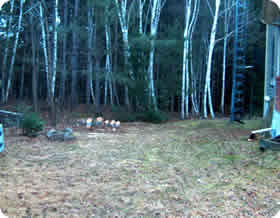 |
Choose a flat and level location close to your electrical service entrance. In my case I had to cut down some Birch trees that were leaning towards the house. The pile of rocks in the foreground cover the exposed wellhead. |
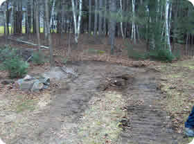 |
After the stumps were cleared out, and the area levelled, it looked like this. While the excavator was busy, I constructed some frames of pressure treated 2x6 to hold the gravel base for the generator and the propane bottle. The frame was roughly 4 by 5 feet for the generator, and 3 by 3 feet for the propane bottle. The bottle is to be no closer than ten feet to the generator (by code). |
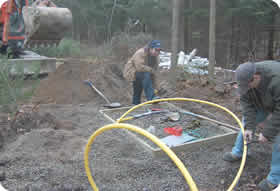 |
Here you can see the gas line being installed. To the right of the excavator bucket is the area where the propane tank will be installed. The worker in the light brown jacket is standing in the trench where the gas line will be buried. Both the gas line and the electrical TEK-90 generator feed cable were buried at least 18 inches below grade. |
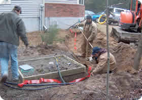 |
Here is the trench is being filled in between the generator base and the service entrance on the house. You can see the electrical feed and control leads, as well as the gas fitting in the foreground. Lying on the gravel is the ground plate that will be buried and the ground (green lead) that will attach to the frame of the generator. The red plastic tape is buried at a depth of 6 inches to warn future excavators that there is a power or gas line buried beneath. |
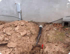 |
Finally a hole was drilled near the existing service entrance to bring the generator leads into the basement beside the existing 200 Amp service panel. The PVC elbow that is shown is the existing service feed, it goes underground, then three feet to the left and then back up to the meter base. The small black wire shown running across the picture is the telephone cable. Somehow it never got buried that deeply. We ran into it about 3 inches down when digging the trench. I will have to re-bury it in the spring. |
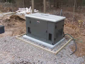 |
The generator arrives! and is placed into postition. Now it must be wired, and the optional cold start kit installed. The last step is to convert the fuel source setting from Natural Gas to Liquid Propane. Once the propane bottle arrives, the unit can be commissioned. |
| Here is what the electrical meter and area looks like after the transfer switch is installed and the service entrance moved to the new disconnect switch.. The meter was moved to the right of the downspout, and the old service entrance plugged with foam. In the spring I will mix some grout and fill the holes to match the rest of the exterior. | |
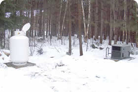 |
Here is the outside view after the installation is complete. What a difference 48 hours makes in Northern Ontario. The propane bottle has arrived and will be filled shortly. There was enough fuel to commission the generator, and only one setting had to be changed. It arrived with the frequency set slightly high (my computer UPS complained at 63Hz) but once the no-load frequency was adjusted to 61.5Hz, the UPS quit complaining. Fully loaded, the generator's frequency was very close to 60Hz. |
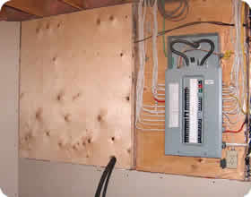 |
Here is the existing electrical panel with safety cover removed on the service feed. You can see the generator feed and control cables coming though the backboard that I installed. The grey cable coiled above the distribution panel will connect the load shed relay installed in the electric furnace. The load shed relay cuts off two of the three elements in the furnace, dropping the furnace load from 15kW to 5kW when the thermostat is calling for heat. This ensures that the generator will not be overloaded, and provides enough heat to keep the house above freezing in the winter. |
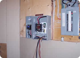 |
Here the automatic transfer switch is being installed, with the new service disconnect switch (E.S.A. requirement) mounted to the left. This disconnect is between the power meter and the automatic transfer switch and is used to isolate the generator and house from the electrical power grid (Hydro One). The automatic transfer switch is a "break before make" type - it connects the common point (my house) to either the power grid or the generator, but does not allow the two sources to be connected together. |
| Here is the completed transfer switch installation with safety covers removed.. The feed from the power meter enters the service disconnect at the top, feeding through the switch and into auto transfer switch on the upper contacts. Its a little difficult to see, but the generator feeds the transfer switch from the bottom to a set of contacts mounted above the transfer switch output contacts which are wired to my distribution panel.. The "old" 200A main circuit breaker is now used to isolate the house from any power source should it be required. The cream coloured plate on the box above the transfer switch is the remote status indicator for the generator. If a fault should occur, it will signal the fault, so it can be investigated and corrected. The "before generator" and "after generator" wiring schematics are shown here. |

